


This is in continuation to the paper published in the February Issue, on BULL-Nose (roof edge) and Temple leaf with roof skylight, as special architectural features of Rajiv Gandhi International Airport, Hyderabad. In this article, the special steel structures specific to airports called, “THE ATC TOWER TOP”, are taken up.
ATC TOWER TOP: “Air Traffic Control” Towers are tall tower-like structures, which are primarily intended to receive or transmit, communication signals between ground crew and Air craft pilots during landing and take-off. Mostly, they are hollow cylindrical tall pillars designed as free-standing RCC cantilevers, with access lifts and a staircase inside. On top, a three-storied Control station with MEP and HVAC Services on one floor, the restrooms and cafeteria, etc., on the second floor, the control Cabins on the third floor and Communication Antennas, OHT and LMR (Lift Machine Room) on the terrace.
This Tower top structure is designed with Steel frames, composite metal deck floors, and Glazed envelop for all-around visibility, for ease of construction, and maintenance. Cold-formed steel or Aluminium profiles are used for supporting the frame of Glazing. The total circular frame is braced all around, with high strength steel tie rod bracing. The height of recent towers of International Airports is kept at about 100M, the tallest at Kaulalampur, Malaysia being 133.8M. This entire utility and the concrete column below, are merged in to different beautiful architectural shapes like wine cups, flower vases, sengol, etc., which highlight the entire airport campus, being the tallest structure.
Determination of Height of Tower:

- The line of sight drawn between the operating level height and runway end is minimal 1°.
- The operating level has direct visibility on entire active pavement, including runways,
- taxiways and platforms. If not, additional height will be added to the tower. ATC tower height doesn’t interfere approach surface (if so the tower must be marked).
- ATC tower does not interfere the misses approach path (if so the tower must be marked).
Tower top Structure Details: The Architectural features need complex Steel structural arrangement for proper support of Glazed cladding and specially shaped terrace parapet, and antennas. The cabin Interior is planned to accommodate the required number of computer stations meeting necessary ergonomic standards. Curved mono rails are provided at different levels to hold the maintenance platforms/crew for cladding maintenance.
The cab size of an air traffic control tower is dependent on the number, location and size of control positions and consoles. Therefore the towers are classified into 3 main categories by the FAA (Federal Aviation Administration) and ICAO (International Civil Aviation Organization): Low activity, intermediate activity and major activity. It is important for the designer to review the current and projected future air traffic activity because the future expansion of the cab is difficult to realize.
Next to this, the layout of the working positions within the tower cab and operating consoles will be determined in relation to the maneuvering area and the frequent approach direction. The table below gives indications of the minimum required surface of the control cab in square meters. Note: these values are determined by the ICAO, in reality, these values don’t differ much from the FAA categories.
Control cab Design:
The height and the size of the control cab are determined in the previous sections. The third important design feature regarding the control cab is the visibility from the inside of the cab to the outside, overlooking the airport. The aim is to provide maximum transparency and eliminate glass reflections using the following design principles.
The control cab should have a 360° visibility range. Avoid structural elements (columns) in the middle of the control cab, preferred only in the façade. The facade’s structural elements in the façade should be integrated with the façade structure and be multi-functional, e.g., water drainage and utilities. Limit the number of vertical supports. The vertical supports should be kept to the smallest feasible diameter. The ceiling could slope upwards at its perimeter to enhance upward visibility
The glazing should slope outwards with 15 degrees (recommended) from the vertical to eliminate reflections. Circular glazing rooms are preferable regarding glass reflection compared with square glazing rooms.
Tower Design:
Structural Design – The typical 100m tall air traffic control tower function is split into the “stalk” which is approximately 10m wide by 22m long and at the top of this is a 6 storey high (excluding roof) “cab”. The stalk is to be built of in-situ concrete.
The cab houses various rooms and facilities including the visual control room which lies approximately 95m above ground level and 5m below roof level. The upper 2-storeys of the cab are steel framed, in order to achieve small lightweight vertical columns, minimizing visual obstruction for the visual control room operation and offering 360 degrees panoramic views, required for air traffic control operations. The lower 4-storeys of the cab are concrete frames, supported by the stalk below. A deep foundation with piling, is provided.
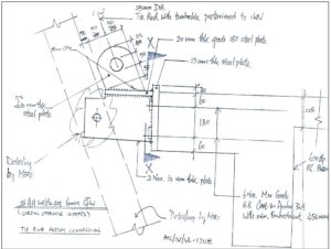
Tie Rod Bracing of Tower Top (Example RGIA-Hyderabad) :
This bracing is intended to control abnormal deformation of the Steel Frame of the Tower top structure which could result in sudden brittle failure of the Glazed Cladding of the Tower top. HYSD Fe500 Gr. 25mm Dia. Steel Rods are used to effectively brace the structure. The Rods are also modeled in the STAAD analysis of the Tower Structure.
Composite Metal deck floor Design:
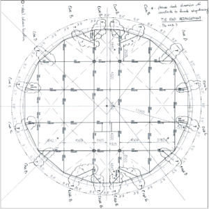
Typical floor beam layout and column positions are shown in the drawing Steel girder sizes are mentioned and tie rod locations are also shown. Mullions and tie rods provide edge supports to the periphery of the floors.
Special Wind and Seismic Design requirements:
FINITE ELEMENT MODELS (Example Malaysia KLIA Tower): In this study, two FE models are created. The first model is a linear FE model and is employed to run modal analysis. The second model is a nonlinear FE model and is used for running nonlinear time history analysis. Linear and nonlinear FE models are created using ETABS, and Perform 3D software, respectively. Figure 5 shows the created FE models in 1st, 2nd and 3rd flexural modes. It should be mentioned that, obtained results from both soft wares were in close agreement. All openings in the concrete core and slabs are considered in FE models. Piles and foundations are included in both linear and non-linear FE models. In order to investigate the effect of pile-foundation flexibility on the dynamic characteristics of the tower, two more fixed-base linear and nonlinear FE models are created. In the linear FE models, beams and columns are modeled by frame elements and concrete shear walls are represented as shell elements.
Construction of Tower (Example IGIA – Delhi):
Both slip-forming and jump-forming are considered, however, the curved core and limited space in the core meant that this would be extremely difficult. Hence a full scaffold solution seemed to be the most viable.
The weight of construction elements was limited to the capacity of the tower crane. ALFA Hydromatic A807 tower crane was provided, to the required height. The crane can safely carry 6 tonnes at 17m and 1.5 tonnes at 60m radius.
Conclusion: The ATC towers are Special Airport Structures involving intricate architectural and functional requirements. Being the tallest structure of the total campus, needs special attention of aesthetics and critical Wind Dynamic and Seismic design criteria. Other critical design aspects are, the cabin design with ergonomics and meeting 360O visibility requirements for the ATC crew needing all round Glazed cladding with special rod bracing. In the next Article on Airports, we deal with the Special structures called “Aero Bridges”.
CONTRIBURED BY-
Dr V.V.V.S.Murty, Dean, R&D and Professor, Siddhartha Institute of Eng. & Tech. Hyderabad


I like this website it’s a master piece! Glad I noticed this ohttps://69v.topn google.Expand blog